
Scarlett : We’re in such a terrible storm. Oh, Rhett, where is everybody?
Rhett : They’re all gone with the wind.
Scarlett : Then, at least let’s have a nice dinner tonight. Where’s that scrawny chicken?
Rhett : The storm got the chicken. It’s gone with the wind.
Scarlett : Then, let’s have a radish.
Rhett : The radish field was blown away, then washed away, so…no radishes. They’re all gone with the wind.
Scarlett : Then, let’s go to Tara.
Rhett : Tara’s gone with the wind.
Scarlett : Why do you keep saying ‘gone with the wind?’
Rhett : It’s sort of a theme…if you think about it.
Scarlett : Oh, Rhett, I’ll think about it tomorrow.
Rhett : Frankly, my dear, the dam is about to break and I don’t think there’ll be a tomorrow.
Scarlett : As God is my witness, I’ll never be….what’s that noise?
Rhett : Dam, Scarlett!
This topic is located on the Home Building Timeline, beginning with the construction phase SHELTER at grid location S-17.
NOTE : This is a free article. Read it all you want and share it with all your friends, so they can read it for free, too. It will remain free for an indefinite but long period of time.
In 2005, Category 5 Hurricane Katrina brought a colossal amount water in two forms: storm surge and downpour. Crossing the shoreline, she lifted the whole sea over the top of surge-protection levees, a type of dam, and in the process made gaps so large the next surges used them like wide-open passes. The downpour was epic for both volume and area. Unrelenting rain fell across the entire Mississippi River delta, extending, as a single storm, 150 miles inland.
The same levees, which were intended to keep the sea out, performed in unexpected ways. At the same time the lowland bowl of New Orleans was filling with rain from sea and sky, 150 miles inland which is uphill, the torrent overwhelmed all flood-control measures in the form of more breached levees. Individual flash floods merged and drained directly into the already flooded city. Levees were overflowed and eroded. The erosion was just enough to allow additional water to flow in. Then the levees did their job, only in reverse. They held the flood in place, but inside instead of out.
Pumping systems, the ones still working, could only draw water from low places, then push it over dams into next-door reservoirs from which it drained, through gaps in the levees, right back to the low places it just left.
In 2018, video posts on social media, which appeared even as Hurricane Michael roared across the Florida panhandle, revealed buildings falling down, and whole structures lifted up and away. Also revealed was that the hurricane was an almost irresistible force moving against newly-built structures, which proved to be not-so-immovable objects.
Katrina was an object lesson about the effects of inundation by water. Michael was a demonstration of the power of wind.
Now, the second-guessing begins, and the blame for much of the damage is being placed on the failure of the building code to require better construction practices, mostly by contractors (term used loosely) who have turned out to be the sorriest excuse for ‘builders’ ever seen in America. The failure is not of the code, itself, but of the breakdown of implementation of best practices for overseeing any given project, by a competent, supervising builder (term used correctly).
Many individuals who decided to call themselves home-builders, after about 2003, actually have no experience at all with the how-tos of construction. Instead, they practice the business model of drive-by supervision. From the seat of a truck they’ll carefully check to see IF something is built, not HOW it’s built. They are so ignorant, they don’t know if it’s built by the plan, by the code, or by any accepted standards, whatsoever. They don’t belong in the building business; and they aren’t building homes of good quality. They are wasting time, materials, and money. Their customers are being cheated. Society and insurance companies at large are being defrauded for having to pick up the tab to clean up their messes, projects which have too easily washed away or blown down, leaving huge masses of debris choking streets, yards, and waterways.
The code already requires very good practices for the installation of storm-resistant assemblies. But what does it matter when those practices are ignored?
Here’s just one example :
A video of Hurricane Michael, shared on a popular social media platform in real time during the storm, shows a row of seaside homes being buffeted by the gale. One middle house is under construction. The wall and roof framing are completed, but (because the house is under construction) only an unfinished skin of plywood covers the walls and roof. Suddenly, the second floor is lifted several feet, torn loose by the wind. It shifts a few feet to the side where, released from Michael’s grip, it falls, part on its own remaining structure, and part on the house next door. By the way, this was the only apparent damage to the house next door.
The wind-tossing of this house may have been preventable if the building code had been followed. The code requires that homes built in high-risk storm zones, of which the coast of the Florida/Alabama panhandle is one, must have a net of steel anchor-cables installed. These cables, embedded into all edges of the foundation, traverse through the walls and over the roof, connected at many points to the framing, to be embedded again on the opposite edge of the foundation. The idea is to form a net of steel, the sole purpose of which is to hold the house down in high winds.
But in the video, during the flight of the second floor, it’s raised high enough to show only empty space, beneath. There are no cables dangling in the wind. There is no steel safety net. The building code was ignored.
Of course, even for projects where the code is completely and correctly built-in, a direct hit by a strong storm of any force or category will cause severe damage.
A Katrina-sized, Michael-empowered weather phenomenon doesn’t simply blow over an area. It scours the surface and leaves it bare. Still, random eddy’s and whirlwinds within the storm make it possible for catastrophic currents to blow down even correctly-built structures, while lesser winds swirl by others only yards away, leaving them intact.
The building code, as it exists right now, when followed, is a very good guide for building substantial homes, which might be survivors of the storm. But when the rules are skipped over, the house just might skip away.
The methods to build a sturdy home are so simple. The only real failure is to not follow them. The strength to stay in place is based on making connections between the parts of a structure to create resistance to floating away and flying away, falling over, and collapsing.
The Strength of Float-Away & Fly-Away RESISTANCE
This topic is located on the Home Building Timeline at grid location BB-16.
As important as it is to hold a structure up, it is just as important to hold it down, in place, resisting the forces of Nature that might try to carry it away on a surge of water, or a burst of air.
Hold-Down devices include anchors embedded in foundations and concrete walls; cables and cable-nets, which lash wall and roof framing to the foundation; steel plates bolted or welded as part anchor systems; and many more.
Check with your local Building Department to find out what type of structural resistance might be required for any given project you undertake.
The STRENGTH of POSTS, COLUMNS and PIERS
This topic is located on the Home Building Timeline at grid location T-16.
In this context posts, columns, and piers transfer weight and force from structures above, straight down, to structures below.
A vertical component must do more than transfer weight in a straight line. It also has to be strong enough to resist compression and bending, as it supports the weight of the structure.
Example : Under a deck, skinny posts that appear bow-legged – the posts are too weak to support the weight of the deck, and are bending under the pressure, and are failing.
Posts must have enough substance to carry a designated load, as well as resist bending and bowing under that heavy weight.
CONNECTING STRUCTURE TO POST : Beams connected to each other, and to posts, MUST NOT rely on just bolts and nails for support and anti-slipping. Beams must rest on another structurally capable part.
Remember – IF IT WON’T STACK, IT WON’T STAY.
STILTS : A Misunderstood Post
Whether the objective is to keep a home above flood waters, or storm surge, or beyond the reach of wild animals, a handy construction method is a house on stilts.
The Typical Stilt-House Mistake : Stilts are wrongly set on weak footing anchors ( diagrams A & B below ). The stilts are cut off at floor level, and a platform is placed on top of the stilts. A house is built on the platform. This creates too many points of connection, all of which can fail in fast water and high winds.
TERRIBLE MISTAKE ( diagram C below )
A NON-STRUCTURAL fence-post stake (C) should never be used for structural purposes. This has no strength in any direction at all, and is only good as a fence-post-butt holder.
The Perfect Stilt House : Heavy-Duty Stilts of wood or concrete, (diagram D below with wood shown) deeply embedded in the ground (in concrete is even better), extend up, past all floor levels, to the top-most point of every wall, including gable roof peaks. Then the entire structure is built within the skeleton formed by the stilts. (diagram below actual)

POST ANCHORING : CONNECTING POST TO GROUND
This topic is located on the Home Building Timeline at grid location U-17.
This process must meet two objectives – 1) to keep posts from shifting side to side; 2) to keep a post from lifting up, thus allowing a structure to float off, or blow away in fast currents of storm water and wind.
Posts are anchored in two basic ways:
- Metal anchors utilizing strapping, bolts, nails, screws, or flanges set in concrete.
- The actual post fully and deeply embedded in the ground.
Different Options for Different Purposes :
LIGHT-DUTY Metal Post Anchors ( diagrams A & B below ) are well suited for top-down loads, and resisting light, side to side bumping. However, they DO NOT resist uplift or severe lateral forces from fast moving wind, flood water, or storm surges. In such severe conditions, small bolts, screws, nails, and thin metal plates will shear off, causing failure of the post and any supported structure. This is because all the force of nature is concentrated against small points of connection – bolts, nails, screws, and rods – which can break easily.
HEAVY-DUTY ( diagram D below ) – For structures, such as boat docks and Stilt-Houses, by a river or on a beach, built to withstand severe forces, the only acceptable method of anchoring the post (stilt) is to deeply embed the post in the ground. Then, Nature’s forces of fast moving water and wind are resisted by the strength of the post combined with the whole immovable earth it’s attached to.


The STRENGTH of BEAMS
This topic is located on the Home Building Timeline at grid location V-16.
A Beam, often in combination with one or more columns, substitutes for a wall. But, unlike a wall which has supporting studs every few inches, a beam may go many feet with no support at all. So, it has to support itself and everything above it.
The key to the strength of a beam, no matter the material, is its top-to-bottom dimension (depth). A beam on edge is stronger than the same beam laid flat. The flat version will bend a great deal.
Deflection (bending under weight) is the term most often used to describe how a beam responds to the structural load it supports. Less deflection is better.
Calculating the combination of Structural Weight, Column Distribution, Beam Spacing, and Deflection is a job best left to a qualified Structural Engineer. Getting it wrong can be disastrous, even fatal. Hire a pro.
The STRENGTH of FLOOR JOISTS, FLOOR SYSTEMS, and FLOOR PLATFORMS
This topic is located on the Home Building Timeline at grid location R-19.
In this context the subject is materials other than concrete slabs. Floor joists, floor systems, and floor platforms span empty spaces, supported only at the edges, and sometimes by posts, piers and beams in the middle of the span.
The strength of any joist comes from its depth – the measurement from top to bottom; from the ability of the joist material to resist bending, compressing, and tearing, when weight is applied; and from the spacing of the joists. Each floor joist carries a small portion of the total weight.
A Floor Platform, in this context not a ground supported slab, can be any system that provides support for wall and ceiling-roof structures including :
- Wood Joists and trusses
- Steel trusses
- Concrete, precast planks
- Self-supporting concrete floors
- Timber and plank pairings
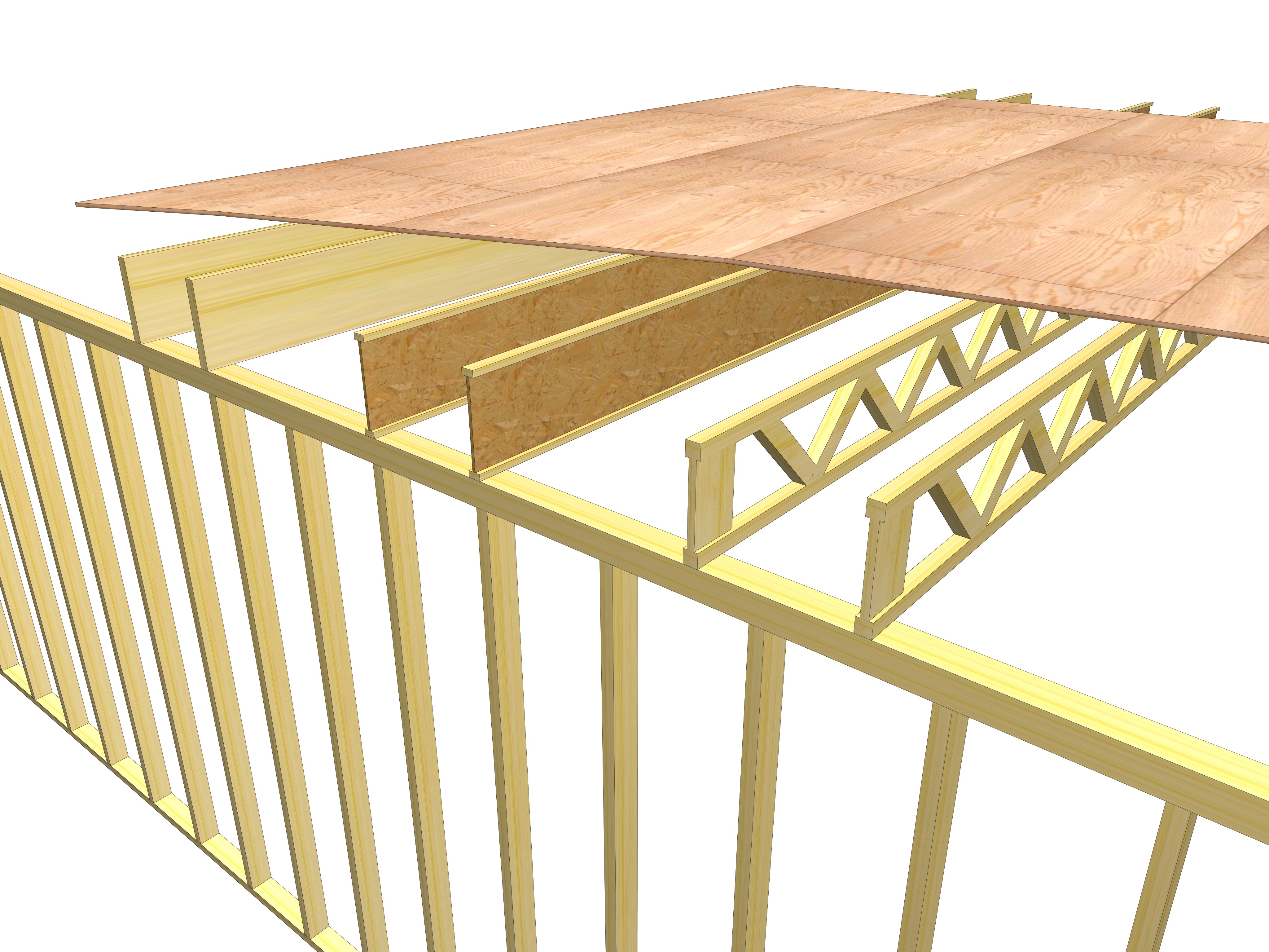
Below, left to right : Solid Wood Floor Joists, Engineered Wood I Beams, Engineered Floor Trusses
CRITICALLY IMPORTANT :
Assure that EVERY floor framing and forming component is square, plumb, and level.
Sub-flooring, the layer underneath the finished flooring surface – in this context, can be any system that provides support for other structures, such as walls and the roof. If the subfloor is too thin, the floor will be spongy to walk on, and too weak to support furniture, and structural loads.
Some subfloor examples are :
- Plywood sheets
- Particle Board sheets
- Whole wood planks
- Concrete Planks – like a parking deck
- Grout ( concrete ) poured in place over a temporary ‘form,’
The STRENGTH of WALL FRAMING
This topic is located on the Home Building Timeline at grid location W-16.
Wall Installation, in this context, can be any system that provides support for ceiling-roof structures including :
- Wood studs – Stick Framed or panelized.
- Post and Beam
- Steel studs
- Logs
- Concrete block units
- Concrete Panels – pre-made then set in place
- Stressed Skin Panels – A stressed-skin panel is an insulated building panel that is comprised of a foam core sandwiched between two “skins.” such as plywood or another composite material.
- Rammed Earth
- Fitted stonework / Can be real stone / Can be a concrete product that resembles stone
In this context the subject is materials other than concrete. Wood or steel studs combine individual strength with other studs in order to support the weight of any structure above, then transfer the force of that weight downward to any lower levels and the foundation.
Each stud can carry a small portion of the weight of a building. It takes a lot of wall parts working together to make a building strong enough to hold up its own weight, as well as stand against the fury of nature.
The strength of wall framing comes from the combination of three traits :
- Its nominal dimensions – 2×4, 2×6, 2×8, etc;
- Its height – the measurement from top to bottom, often coinciding with ceiling height;
- The horizontal spacing of the individual parts – studs – of the wall. They have to be spaced frequently enough so they can work together to support the weight of any rooms and roof above.
Wall-framing must be strong enough to resist bending, compressing, twisting, and breaking when weight is applied straight down; and endure lateral shear-forces from wind and water.
The spacing of wall studs is commonly measured from the center of one stud to the center of the next, referred to as center-to-center spacing, and abbreviated as ‘c-c’.
Guidelines : The taller the stud, the larger it has to be.
- Wall/Ceiling height up to 11’ – 2×4 studs at 16” c-c.
- Wall/Ceiling height 12’ to 20’ – 2×6 studs at 16” c-c.
- Greater heights and loads will require special engineering, as will some local design standards, which could include closer stud spacing, like 8” or 12” c-c; or engineered, finger-jointed studs; and/or double-thick wall construction; and multi-level cross-bracing (aka firestop braces).
Firestop Bracing is made of short pieces of stud-lumber attached between studs to stop drafts from carrying fire through the empty spaces inside a wall. This same firestop bracing also adds strength to walls by preventing load-bearing studs from bending toward one another.
Bracing the Wall – Several studs work together to carry weight, but they can’t help each other stand up straight. Braces keep a group of studs from leaning over.
- Diagonal Braces may be wood, plywood, OSB, or steel straps. Wood braces (aka ‘let-in’) are installed along the length of a wall, by cutting a notch into each stud, then the brace is recessed into the notches (let-in). The diagonal brace prevents stud-leaning by creating a series of structural triangles, Nature’s strongest shape.
- Solid Braces
- edge-to-edge diagonal planks may brace corners and short walls, where space is too limited for a ‘let-in’ brace.
- Shear Panels may be plywood, OSB board, steel plates, or specifically purpose-engineered.
- Corner Bracing keeps a structure from twisting down, by locking corners so tightly, they can’t move. Every corner has its own possibilities for the bracing method.
A Common FRAMING-INSULATION-COST FLAW –
A common technique to increase insulation is to use 2×6 studs for all exterior wall framing. 2×6’s cost more than 2×4’s, so to save money the spacing of the 2×6 studs is often increased to 24” c-c. There’s nothing wrong with this by itself, but there’s an often-overlooked flaw to this plan. Wall surfacing materials, like exterior siding and interior drywall and paneling, are manufactured to be supported by wall attachments every 16”. Studs spaced at 24” c-c mean attachment-spacing will exceed the material’s own ability to remain sturdy and straight, causing the material to become wavy and ugly. This must be offset by adding a stronger backing material, like plywood or OSB panels, underneath the surface. This adds cost and will offset any utility-bill savings created by the extra insulation.
The STRENGTH of CEILINGS
This topic is located on the Home Building Timeline at grid location Y-16.
Ceiling Installation can be any system that provides a finishing touch, and a certain ‘feel’ to a room, whether it’s the formal elegance of a high ceiling adorned with intricate crown molding, or the rustic charm of a steeply pitched vaulted ceiling supported by hewn timbers. Ceiling Systems can be separated room by room; or traverse several rooms, combining many spaces into one.
Framing Materials used for Ceiling Systems may include :
- Wood or steel joists and trusses
- Engineered Concrete poured in place
- Concrete Planks set in place (like a parking deck)
Wood and concrete Timbers for Posts and Beams
Framing Methods : Ceilings can be built in several ways:
- Wood joists with ceiling material on the underside.
- Wood joists or beams with ceiling material on the top.
- As the lower cord of a manufactured roof truss.
- Engineered concrete (grout), poured in place.
- Concrete Planks set in place (like a parking deck).
- Logs placed side-by-side to make a ceiling or floor.
- Hardened Glass Panels embedded in a framework.
- Many more possibilities.
Surface Materials ( the part you see ) may be anything which the ceiling framing can hold up. It’s important to decide ahead of time, and include in the plans, whether the surface material will be light or heavy, so framing joists and braces of the correct size and strength can be selected.
A Suspended Ceiling, often overlooked and under-appreciated, is a secondary, non-structural system, like grid-supported acoustic ceiling tiles, which is actually held up by being strapped to a structural ceiling system, overhead.
About Ceiling Structure, Stacked Rooms, and Attics :
One story homes generally have ceilings (attic floors), which are only strong enough to support the drywall ceiling of any given room, but offer no structural assistance toward supporting any roof or building load.
In multi-story homes, the ceiling of a lower room may be the floor of an upper room or an Attic Space used as living area, like a Bonus Room, a Playroom, or Home Theater.
Plan Ahead : It’s important to make all structural design decisions before construction begins, so proper framing materials can be chosen to support the weight of any thing or activity that might be above the ceiling.
The STRENGTH of the ROOF
This topic is located on the Home Building Timeline at grid location Z-16.
Roof Installation may be any system that provides coverage and protection for components below. Roof Systems can be separate or combined.
Materials and techniques used for Roof Systems may include :
- Wood Rafters and joists
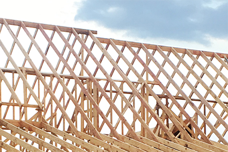
- Site-framed, or Manufactured Trusses
- Steel
- Timber beams and rafters
- Stressed-Skin Panels – A stressed-skin panel is an insulated building panel that is comprised of a foam core sandwiched between two “skins,” such as plywood or another composite material.
Soar Like A Bird – A typical roof system has sloped sides and a peaked ridge, so water and debris will fall off. That same high-in-the-middle shape closely mimics the contour of an airplane wing (diagram below, actual). As wind from one side blows across the ridge of the roof, low pressure is created on the other side, causing ‘lift’ , the most important physics-component of flight (diagram below, next). When wind-speed is fast enough, a poorly connected roof system will be torn from its framing connections, and sucked into the sky to soar on wind currents, just like a bird.


Connections – A sturdy roof depends on a sturdy house. All connections that hold the various framing parts together, foundation, floors, walls, ceilings, and roof, must be sufficient to resist the forces of Nature. The most common framing mistake is to use too few nails and bolts, or to use slender nails when hefty screws are needed, or to fail to understand the structural demands of any given home-building situation.
A sturdy house and roof have the right connections at all the right places, to better resist the break-apart and fly-away performance failures caused by Nature’s blowing winds and rushing currents. Forces to consider for shallow and steep roofs are:
- Framing Weight of the roof itself.
- Shingle Weight – light or heavy, like slate, or tile, or foam.
- Water weight from torrential rain. A moderate rain can place 2000 pounds per minute on a typical roof. It may drain off, but it’s falling right back, again.
- Snow and Ice weight, plus Avalanche.
- Wind Shear, sideways and uplift from sustained surface winds, sudden gusts out of the blue, severe storm turbulence, tornado, hurricane.
- Earthquake.
- Flood and Tsunami – fast and deep – sideways and float-away.
- Falling Items – whole trees, tree limbs and branches, boulders rolling downhill, flying debris, storm-tossed vehicles, even other houses dropped from the sky, and more.
Points of Roof Connection –
- Rafters anchored, at the bottom, to ceiling joists and walls.
- Rafters anchored, at the top, to the ridge beam. A common roof framing mistake is too few nails at the ridge.
- Decking poorly fitted to rafters. Each sheet or plank of decking must have enough overlap on the rafter’s edge to provide enough surface for connecting nails to sink into and ‘bite’ the rafter.
- Decking fastened to rafters. Another common roof framing mistake involves too few decking nails, and nails which are too slender and short.
- Insulating Board must be installed with nails or screws long enough to go through the surface material AND the insulating board AND still ‘bite’ properly into the framing component.
- Moisture Resistant Barrier
- Surface Materials well-fastened to decking.
- Shingles or other choice of surface
- An installer must be able to tell the difference between a nail hitting solid wood and one hitting empty space.
Roof Work-Load In the Moment – A Moment of Force is the sudden infliction of stress and pressure, which lasts only a few seconds. A correctly built roof system must last a long time to protect the house during its entire life.
Also, a roof must be able to resist the Moment of Force, the sudden, momentary natural attacks which Nature will surely bring.
Objectives are simple.
Any structure, especially in a hazardous zone, should have the strength to stand on its own, to stay in place, and to resist flying off in wind and floating away in a flood; and to not be part of the news, which means home will still be there, tomorrow, after the disaster has passed.
Then can be shared the excitement of Scarlett’s
final words after the storms of her life dissipated,
“Home…I’ll go home.…..After all,…tomorrow is another day.”

NOTE : This article will remain free to read until April 12, 2019. Until then, read it all you want and share it with all your friends, so they can read it for free, too.
just for yourself. to someone who might need help building or remodeling. who needs to see HBT.
Buy a subscription

Give a subscription

Tell someone